Fly's Eye Dome Home

Please wait for images to download

If you would like to donate to further the development of this work click on the button below. Your donation will help bring this work to the public and establish it for posterity.


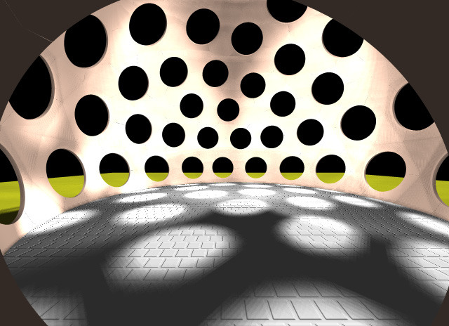
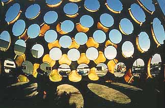
The first image is my new design, while the second image is a picture of the original Fly's Eye Dome designed in the late 1970s. The big difference in the topology of the openings in my design, compared to the original design topology, is that my design excludes the opening at the Icosahedral vertice. This is to provide a continuous, uninterrupted surface for the upper loft as seen in frames 16, 17 , and 18. There is also a secondary reason, the original structure, with the added vertice opening, causes unacceptable thinness of the inter-opening structure. This would not be a serious problem in a temporary structure but I chose to make the structure less vulnerable to loading stresses experienced in high wind and ice load conditions. By eliminating the vertice opening, the structure is more substantial and provides a more architecturally acceptable interior design.

Get QuickTime 4 Movie images require QuickTime.

Click on thumbnails for larger images

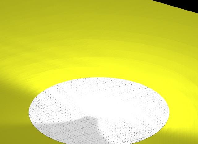
1. view of field of grass with 50 foot tile circle flooring
1962.5 sq ft


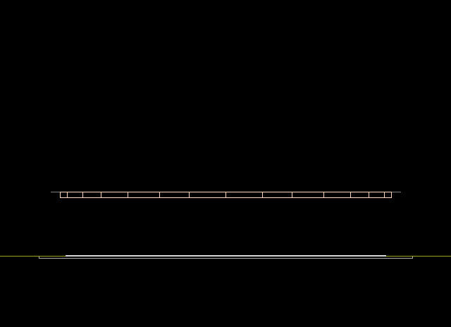
2. Front view of grass with
50 foot tile circle ground level floor; 1962.5 sq ft


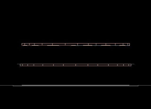
3. Front view of 60 foot diameter first level floor, 2826 sq ft , and
50 foot diameter ground level floor, 1962.5 sq ft


4. Front view of
50 foot diameter third level floor, 1962.5 sq ft , and
60 foot diameter first level floor, 2826 sq ft , and
50 foot diameter ground level floor, 1962.5 sq ft
Total of 6751 sq ft floor space


5. 45°x45° view
50 foot diameter third level floor, 1962.5 - 1/2 = 981.25 sq ft and
60 foot diameter first level floor, 2826 - 1/3 = 1884 sq ft , and
50 foot diameter ground level floor, 1962.5 sq ft
Total of 4827.75 sq ft floor space


6. Back to front view


7. Rendered front view


8. Rendered front view with six foot human figures,
notice that floor spacing is 10 feet


9. 45°x45°, rendered view with six foot human figures


10. Ground level perspective rendered view of lofts with six foot human figures


11. 20 ft from ground, perspective rendered view
with six foot human figures, Sun at 3:00 PM

12. Ground level perspective rendered view
with first set of skin members

13. Next set of skin members added

14. Third set of skin members added

15. Forth set of skin members added

16. Foundation terminated set of skin members added, enclosure complete

17. Without upper loft

18. Without upper & lower loft

19. Ground level outside view, the openings are 8ft in diameter


20. Back to tile floor view

21. Foundation-terminated skin members;
total of 2 different pieces

22. Skin members centered around Icosahedron vertice;
total of 3 different pieces

23. Next set of members centered around Icosahedron vertice;
total of 4 different pieces

24. Next members centered around Icosahedron vertice;
total of 6 different pieces


25. Final members centered around Icosahedron vertice;
total of 8 different pieces

26. Interior-only view

27. Lower stairs

28. Upper stairs and bannisters


29. Furniture

30. Moonlight view from bed

31. Moonlight view, just a little brighter

32. Moonlight view, with lights on downstairs


33. More light

34. Zoom out


35. Ground level view from the backyard


36. Moonlight view from the bottom of stairs

37. 3:00 PM view from the bottom of stairs


38. View from first landing

39. From outside first landing


40. Fly through


41. Sunrise