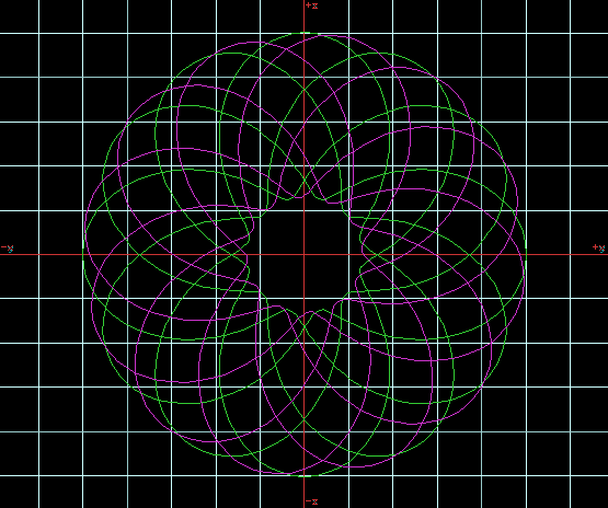
This is my recent work with the Rodin Torus.
This is the top view of the windings.
As seen in the draft below, the geometry put forth in the current documents
deserves some rethinking.
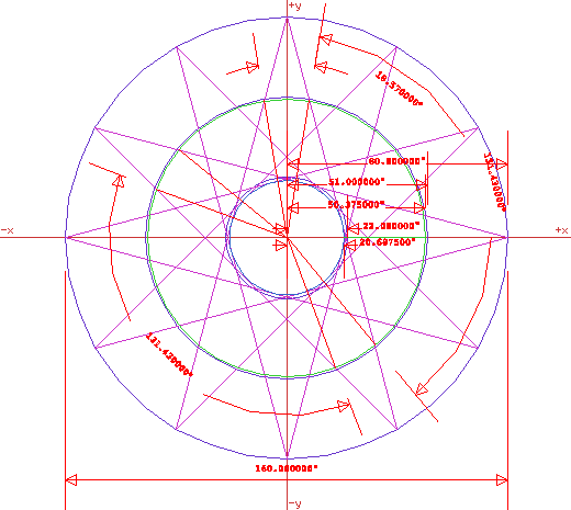
Based on a template circle, colored blue, of 80 units in radius, vectors
are drawn to resemble the trajectories of the windings of the Rodin torus.
These magenta colored lines show the typical vectors spaced around the circle
at 30 degree increments. Based on the recent documents, a circle, colored
blue, was drawn with a radius of 22. However it does not fall into tangency
with the inside radius of the windings. The draft shows that it is a radius
of 20.6875 units. The bisector of this radius is 50.375, colored green,
not 51 as it would be if the dimensions were used in the current documentation.
Based on this assumption, I created a program that created the trajectory
of a sine wave around a torus. With a center trajectory diameter of 50.375
and a radius of 80 minus 20.6875 de vided by 2 which equals 29.6875.
The algorithm uses a trick to simulate the proper quantity of turns in the
winding. A complete 360 degree rotation of the sine wave is completed in
300 degrees of radius of the torus. 300 devided by 360 is .83333333 or
5 over 6. So by modifying the code to the algorithm to create a complete
rotation of the sine wave in just 300 degrees of the torus, a primary building
module of the complete winding can be created.
The parametric equation for a Toroidal Spiral is:
x = (a * sin (c * t) + b) * cos (t)
y = (a * sin (c * t) + b) * sin (t)
z = a * cos (c * t)
a = 29.6875
b = 50.375
c = 2 (number of turns)
This is obviously not a simple task. My extensive experience in coding parametric
equations allowed me to create a quick and dirty solution for the task of
creating a list of coordinates that a 3D CAD program like my copy of formZ
can use. I achieved a modest level of success. I can control all parameters
of the spiral and the resolution of the trajectory to achieve the observed
effect.
However, as seen in the image at the top of this page, this winding does
not resemble the top view of the windings in the current documents, its
trajectory is not a parametric expression, at least not yet. An attempt
should be mounted to create this equation, it appears very difficult.
Below are Quicktime VR movies of the windings. You need the Quicktime Plug-in
from Apple at http://www.apple.com/quicktime
to view the following .mov files. These files are large and take long download
times.
One turn of the sine wave.
A composite of the complete system.
A crude rendered image of thickened wiring elements.
Download the movies by clicking below. They are Quicktime VR .mov files.
Download the primary object movie
Download the complete object movie
Download the rendered object movie
Copyright 1999
by Jay Salsburg
All rights reserved