Details on Doppler Radar Illumination
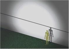
Ideally, a fixed-position motion detector with no beam steering capability would possess an illumination pattern of 10 degrees vertical and 90 degrees horizontal. Since people and vehicles move in the horizontal plane, it is logical to focus the illumination energy to a narrow vertical beam and a wide horizontal beam. For visualization purposes, a virtual environment in a Computer Aided Form Synthesizer is seen in the following images. The ground is textured with green grass and extends 100 meters in front and 30 meters in back and 400 meters wide of the virtual illuminator which intersects a 400 x 400 meter gray curtain 2 meters below a dividing line at the horizontal mid point. A horizontal line on the curtain is level to the illuminator.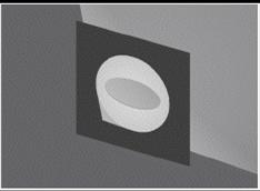

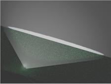
The figure on the left shows a synthesized elliptical mask illuminated from behind which is where we see it here. The light source is conical and is adjusted so that it shines directly through the center of the shadow mask forming an elliptical beam. The two figures to the right are seen from the front side. These two shadow masks form a 30x60 Degree Pattern and a 10x90 Degree Pattern respectively. These two elliptical Illuminating Projectors are 100 meters from the virtual 400 x 400 meter curtain. Notice the tiny spot in the center of each elliptical pattern, these are each a virtual microwave projector.
Description of the
projectors
Close-up of the 30x60 Degree Pattern Virtual Projector. By placing a point source light behind an elliptical hole in a membrane, a virtual projector illustrates the illumination pattern of a typical microwave horn. If the elliptical hole has a ratio of 2 wide and 1 high, placed at the proper distance from the imaginary center of the hole, a reasonable illumination simulator may be used to demonstrate a viable Doppler illumination pattern.
30x60 Degree Pattern 50x100 meters The virtual
projector
produces a + and - 30 degree spot along the horizontal axis of the projector,
the typical illumination pattern of a microwave horn.
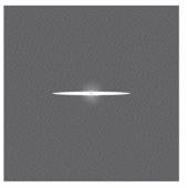
10x90 Degree Pattern 20x170 meters with a ratio of 1 high by 9 wide
(more desirable). The virtual projector produces a + and - 45 degree spot along
the horizontal axis of the projector.
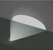
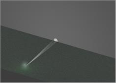
30x60 Degree Pattern. The
elliptically shaped beam leaves the virtual projector as an illumination
beam 30 degrees vertical (50 meters) and 60 degrees horizontal (100 meters) as
measured from the point source illuminator. Notice the small gray spot near the
center of the elliptical light patch. This is the simulated 6-foot human in
Figure 12 standing in front of a simulated curtain that is 400 meters by 400
meters perpendicular to the axis of the illuminator. Notice the virtual projector in
the foreground with the glow of the illuminator emanating toward the curtain.
Again, the virtual projector is 100 meters from the curtain. This relates the size
and scale of the distances described.
10x90 Degree Pattern. The elliptically shaped beam emanates from the
virtual projector as an illumination beam 10 degrees high and 90 degrees wide as
measured from the point source illuminator. This pattern is not typical of
off-the-shelf microwave feed horns. The pattern is almost twice as wide as a
typical 30x60 pattern yet more than doubles the beam intensity along the horizontal
axis and doubles its effective range. This allows better coverage of the area
of interest from the typical 30x60 Pattern feed horn and also limits clutter.
MIR/TM-UWB 50 meter radius Spherical Pattern. (Micro-power
Impulse Radar (MIR) and/or Time modulated Ultra Wideband (TM-UWB)
The down side of MIR/TM-UWBs. MIR/TM-UWBs seem to be the natural
choice for 3D imaging but current COTS (Commercial-Off-The-Shelf) MIR/TM-UWBs have very limited range rendering them inappropriate
for this proposal without further investigation. Limited range is intentional,
for precise imaging with resolutions in unit inches required to detect humans.
It may be possible to create a custom MIR/TM-UWB to be effective at the
illustrated distance of 100 meters and beyond but the author has not discovered a
working commercial unit that specifies this capability without cumbersome,
massive, and awkward apparatus as indicated in the significant Patents. This
effective distance would be seriously impeded by buildings indicating the need
for even higher output power. MIRs exhibit a
limitation, not because of their semiconductors but from the laws of physics,
as follows. Resolution and distance are inversely proportional. The lower
spatial resolution is caused by longer time between return of transmitted
pulses. To image human subjects at 100 meters would take very high-precision
measurement of the return pulses. This would make the impulse
detection scheme very vulnerable to multipath
problems. Many Patents have evolved addressing this problem in a vain attempt
to overcome this deficiency in impulse radar. Many different schemes have been
demonstrated, array antennae, multiple transmitters, array receivers, 3
dimensional processing (reflectograms), orientation
reflectors; all have significant drawbacks for RSTA (Reconnaissance,
Surveillance and Target Acquisition ) compared to Doppler radar.
2x2 Degree Pattern. By placing a 10.525 GHz DIR (Doppler
Illuminating Radar ) in a fourteen inch Direct Broadcast Satellite offset dish or
by using a 35.5 GHZ Gunnplexer where no dish is
required, a spot beam illuminator is formed. This allows the user to illuminate
highly selective distant areas like through doorways, through windows, long
straight streets, long straight roads, highway intersections, tar macadam,
single vehicles or aircraft, and along fence lines.
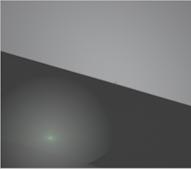
Simulated
subject illuminated by 2x2 Degree beam. At 100 meters, the 2 degree beam is
seen as the bright area in the middle of the image. However, radiation spills
outside the 2 degree arc. This is seen as the glow around the bright patch. The
grass is illuminated in the foreground. By focusing the beam with a dish, the
effective range is multiplied from 30 to 500 times, depending on the size of
the dish, at the sacrifice of wide area horizontal coverage. It is typical to
detect people walking using a 10 milliwatt
illuminator at 500 meters.