Favorite Circuits
E-mail: jay(at)salsburg(dot)com
Schmitt Trigger - Analog
While working for the University of California - Irvine, School of Medicine, I used a DEC LPS11-S or
Laboratory Peripheral System. It had an input interface which allowed the system to measure timing of
events. It had two of these Schmitt Triggers, the software controlled where the triggers go to the LPS's Real-Time-Clock (not to be confused with the RTC in a PC, but is a system in the LPS), could perform many different real-time and long term functions like Frequency, Duration,
and pulse-width. The Schmitt Trigger shown here is the schematic of one of these circuits. It has some very interesting
features. The input connector allows single-ended input referenced to ground, or floating-ground differential
input of signals independent of ground. By using a Tip-Ring-Sleeve plug, the tip and ring can be used as floating
inputs. This is very useful for measuring events that may need isolation or may have high common-mode problems like biological
events in living tissue.
The Slope Switch is very cool. It allows the polarity of the trigger to be reversed without reversing the Slope; Rising or Falling voltage weather above or
below zero volts. It is a little
complex but it is very intelligently designed allowing care free operation with one switch and one Pot. It requires a double-throw-four-pole
switch. This switch is absolutely necessary for effective care free use.
The Trigger pot controls the point, above or below zero, at which the trigger is tripped. The DEC transistors may be
substituted but I do not know what that might be, probably a 2N3906 will do.
The Supply for the Analog circuits should be isolated from the 5 Volt logic Supply.
There is a jumper shown but I do not know what for but appears to adjust weather or not the input of the 1709 OpAmp is pulled more to ground.

Speed Controller for DC Motor Fan, Reversible, Infinite variable speed.
This is a very useful circuit for very precise control of the speed of a dc motor. I built one 25 years ago (1979) and used it to control a forced air ventilation fan in my van which made camping in it tolerable. I have transferred it to two new vans, where it still operates after all this time with no problems except one time when I connected it to the battery backward and burned out the 4049. I replaced it in a few minutes because I had wired it with a socket. Choose a hardy 2N3055 and mount it on an appropriate heat sink for the load it will see. If you expect reverse torque or inductive switching to be reflected to the transistor from the load it would be advisable to place a transients diode across the collector/emitter junctions on the transistor. The capacitor across the transistor quiets the acoustic and electronic noises in the transistor. Remember that the temperature when a ventilator is needed is summertime, when high heat is most needed to be vented by the fan. If you are resourceful you will place the heat sink near the fan to aid its dissipation. I have not experimented with this but I believe a pair of variable electronic resistors can be used to provide remote control or torque compensation etc. for magnetic motors. Also it could be used in Push-Push configuration on each side of the load using two controllers across the motor where the two units are out of phase with each other to aid in isolating the motor. Expansion of this control can be applied to electric transportation motors. The accelerator would be the Pot. By using a 9 volt motor, a 12 volt battery can be used for locomotion. The output is limited to 80% of the power supply voltage because of the turn-on resistance of the transistor. I used a Hayden radiator fan I bought a Pep Boys because of its very robust design. I eventually wore it out after 20 years of continuous operation and bought another replacing it with ease. I augmented the ventilator with its own secondary Marine Deep Discharge battery with a diode isolator from the alternator to run the fan so it would not run down the vehicle starter battery. Another augmentation is a bypass switch so the fan can run directly from the battery.

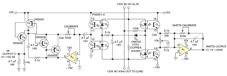
Quad Optoisolator computes Watts and Volt-Amperes simultaneously
The right-hand side, a half-wave analog-multiplier bridge, calculates watts ignoring reactive components in the load. The left-hand circuit is similar but substitutes rectified DC excitation of its half-wave bridge for AC excitation of the right-hand circuit outputting the reactive component. Simultaneous estimation of Power Factor - Watts divided by Volt-Amperes. Put the VA Output and Watts Output of the X-Y inputs of a vector Scope and you have a Real-Time Power Factor Scope for debugging how well your Inverters, Switching Power Supplies, or even those new Compact Fluorescent lights negatively affect the Grid. You will be able to determine how much capacitance to attach to your grid to reduce your Power Factor errors. The circuit is isolated from the AC 60Hz by the Optoisolators. The 10K pot zeros DC offset.